
I am continuing my attempt to self-educate myself at electronics by working through Charles Platt’s book Make: Electronics: Learning Through Discovery, 2nd Edition.
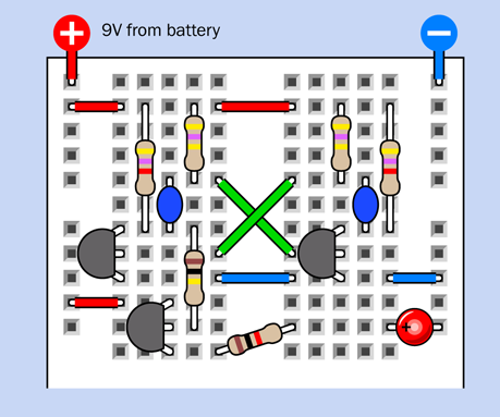
I’m currently working on an oscillator circuit. I was going to take a picture of my actual breadboard with the circuit on it, but this representational diagram from the book is a lot cleaner:
The idea is that when you turn on the power, the red LED in the lower right will flash on and off. The book has a lengthy step-by-step explanation of how the circuit works, with capacitors charging and turning on transistors which discharge other capacitors in a never-ending cycle.
The explanation was a little complicatde for me, so to help my understanding, I wanted to get an idea what was happening at various points in the circuit. I knew that when I built the circuit I could see the voltage on any component lead with my multimeter, but I wanted to get a better mental picture of how things were changing over time. The ideal tool for that would be a digital oscilloscope that can sample the wave form as the capacitors cycle, but I don’t own one, and a decent hobbyist-grade oscilloscope costs more than I’m ready to spend on this.
I decided to try a different approach. Here’s the schematic diagram from the book, showing all the component values and interconnections:
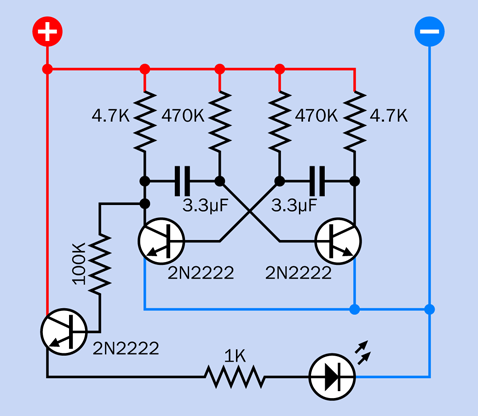
As it happens, I have an old license for the home edition of Wolfram System Modeler. I downloaded the appropriate version of System Modeler and re-activated the license, and I built a digital model of the circuit. (I’ve substituted a resister and a current sensor for the LED.)

Then I ran the simulation and…it didn’t work. Capacitors charged and then everything came to a stop as the simulation assumed a steady state. Every output I sampled was a straight line. Nothing ever changed. The oscillator did not oscillate.
I had never tried to use System Modeler before, so I figured I must have done something wrong. Maybe I didn’t configure the simulation method correctly. Or maybe I setup the transistors wrong. Unlike capacitors, they don’t have simple values that describe their behavior. I had tried entering some values from a 2N2222 data sheet into the simulation, but the simulator used different terminology and had a lot more configurable values than the data sheet had answers.
In any case, I went back to the breadboard and finished plugging in the components, cutting wire, and adding jumpers. Then I turned on the power supply, and…it didn’t work either. I started testing leads with the multimeter, and I saw the same problem. Nothing ever changed. The oscillator did not oscillate.
To make a long story short, it turned out I had used the wrong components. In several earlier experiments I had been using 470 Ohm resistors, and when I saw “470” next to some resistors on the diagram, I used the 470 Ohm resistors again. What I missed was that the diagram was actually labelled “470K” meaning 470,000 Ohms. I was using only 1/1000th the resistance needed.
Once I swapped the correct resistors into the circuit, it worked correctly. The oscillator was at long last oscillating. After about 2 hours of tinkering, I got a little LED light to blink on and off about once per second.
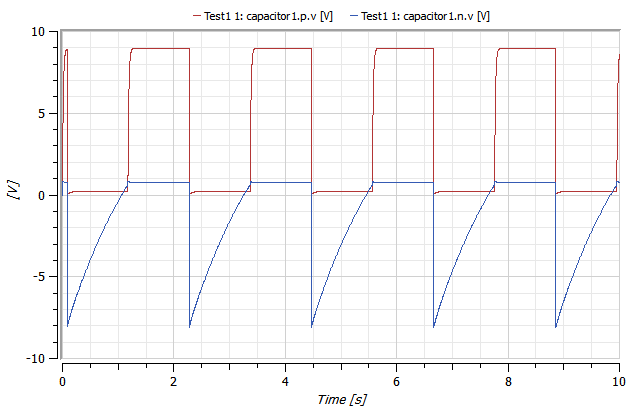
The cool part was that having found my dumb mistake, I could go back to System Modeler and fix the simulated circuit too. I swapped in the correct resistors, and the simulated oscillator worked.
That allowed me to visualize the behavior of the circuit over time, such as this chart of how the voltages changed on both sides of one of the capacitors:
After that, I changed the capacitors to speed up the oscillation into the audio range, which I played through a small speaker to produce a quiet buzzing sound. Then I put the slow capacitors back in the first oscillator and added a second high-speed oscillator powered by the output from the first. This gave me an intermittent buzzer: Bzzzz……bzzzz……bzzzz….
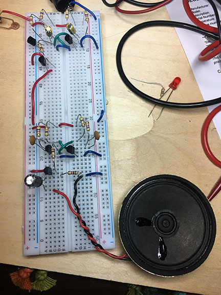
That’s what it looked like when I was done. It’s not very pretty. And I’m not at all handy with electronics, so even this meager accomplishment took me a ridiculous amount of time — several hours spread out over two or three days — but it felt kind of cool to do something I could not have done before, and I felt like sharing.
Amazon has some solder-it-yourself oscilloscope kits $25-40. They’re probably not that great compared to anything else, But the one I’ve used (DSO 138) is miles better than none at all. spend the twelve dollars or so on a real probe, The alligator-clip thing that comes with the kit is the one thing not worth bothering with.
Soldering something that complicated sounds like a recipe for doom. I’ve got a set of mini-hook test leads for my multimeter and they work great. I’d want something similar for an oscilloscope, I think.